Integrated Proyect: Sound Meter

Alejandro Toral López
Versión de la plantilla V02
Laboratory activities.
Hot Air Gun desoldering.
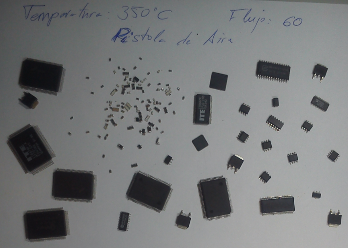
The hot air gun is one of the tools that have been used in the laboratory to desolder components. This tool only is useful with surface mout technology packages. It can be used with Through-Hole componets, but it is less effective. Now The followed procedure is explained.
First of all is necesary to set the air temperature and the magnitude of the air flux. Temperature was set to 350 degrees and the flux was set to 60. Then the hot air gun is set. Now some tips of the desoldering process:
- Try to apply the hot air perpendicularly.
- Use the correct nozzle. It have to distribute the hot air uniformly over the commponent. Very important to change the nozzle when the gun is cold.
- Most of the components need tweezers to be pulled out. Do not hold the component with the tweezers while you are heating, because they are like a heat sink. The component is heated slower and the next components can be burned.
Here there are a photo with the desoldered components:
Desoldering Gun.
The desolderig gun is an specific tool to desolder Through Hole components. It heats the tin of the lead and absorb it. Before start to use it is necesary to configure the temperature of the tool. The temperature value depends on the component that we will desolder. It will have to be higher if the component is a power component, witch usually need more tin to being sordered. In the laboratory the temperature was set to 360 degrees.
About the procedure, we have to put the lead inside the nozzle and move the gun to heat all the tin. When all the tin become liquid we have to push the button and the the gun absorbs the tin. In this moment is very important not to separate the gun from the PCB or move the gun, if not the gun can not absorb the tin. Another issue is the accumulation of tin in the gun's filter. It has to parts: a filter pad and a spring filter. The filter pad have to be replaced if it has a lot of tin. The spring filter don not have to be replaced, unless it is broken. Sometimes the spring filter have to be clened with the assitance of the soldering iron. We heat the stuck tin with the soldering iron.
Soldering Iron.
This is the most basic tool in the hand manufacture of PCBs. Using that tool we can solder both Through-Hole and surface mount components, alghough not all the surface mount packages can be soldered with a soldering iron. For each tipe of package we use one tip or other,if we do not use the correct tip we may destroy the component. Also is important the tempertature of the soldering iron. In the laboratory the temperature was set between 320 and 340 degrees for small componets, SMD componets and some Through Hole, and between 350 and 360 degrees for big components, mainly Through Hole components.
When we solder small components is necesary to use a magnifying glass or a microscope for the smallest.Here we have a video about a SMD component sodered with the soldering iron and a microscope:
Recognition of elements in a PCB
This is the PCB that has the elements that will be recogniced
Known packages are used as references for dimensions and footprint's package type recognition. Because of that some packages are showed in the images. There are some lines over the identified elements that helps to know its dimension and to identificate it. Next to each line there are its aproximate dimension. Now let's see the detected elemnts:
Image 1
1. SOIC-8: These foot print fits with the reference package, wich is a SOIC-8.
2. Passive component package 1206: The lines show the package dimensions and it fits well. The 0805 package do not reach the pads of the footprint and the 1806 is too large.
3. Passive component package 2010: Like with the 1206, the package 2010 is the one that fits better than the others.
Image 2
1. SOIC-14: A SOIC-16 is used as a reference and the leads fits in the footprint, so we can say that this foorprint is for a SOIC-14.
2. SOIC-8: It has the same dimension that a SOIC-8.
3. TQFP-32: The estimated dimension is the same that the dimension of the side of a TQFP-32 and the same happens with the distance between leads.
4. SOT-23: The distance between the pads fits with the distance between the leads of the package.
Image 3
1. TSSOP-48: .
2. Center: package 1806: It can be the package 1812, but it is too much wide.
2. Sides: both are the package 1206.
Image 4
MQPF-144: The reference package is The pachage MQFP-100. Other posibilities could be the TQFP-144 and the LQFP-144, but the dimensions of these packages do not fit with the foot print.
Integrated Proyect
Objective:
The objective of this proyect is to build a system that measures the sound qualitatively, displaying the sound level in a LED bar. Also it provides the possibility of filtering the measured sound with two controls, one for trebles and another for basses. Furthermore it has another control witch let us to change the maximum level that we display.
Comentar qué se quiere realizar con el proyecto.
Se pueden incrustar imágenes (tamaño máximo en horizontal 490 pixeles)
Design Stages:
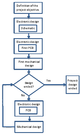
- Proyect Objective definition: Before the mechanical or electrical design is necessary to state the objective of the proyect. In this case: build a device that will be capable of measuring the level of a sound and show it in a LED bar. Also there are three controls. One for the maximum level that will be displayed, and two that controls the behaviour of an filter placed after the capturing stage.
- Electronic Design, Schematic: Designing of the circuit that implements the device's functions.Only one version of he schematic has been done.
- Electronic Design, First PCB: After design the circuit we design the PCB where the circuit will be implemented. It was done before the mechanical design because it adds requirements to the box that contains the PCB.
- First Mechanical Design: Once the First PCB is designed a first box design is developed. After that, if the design is ended, the proyect finishes. However more than one chages were done in the PCB. That implies that changes have to be done in the box too.
- Electronic Design, PCB: In this proyect there have been three PCB versions. Changes are done due to frabrication issues that imply changes in the box and these mean changes in the PCB.
- Mecanical Design: Due to fabrication issues, PCB changes or both the box is required to be redesigned.There are three box versions.
Mechanical Design
In the first design there were two options for the box's shape: square and round. Finally round box option was choosen. The reason of that decision is that a round box does not look like a clasical electronic product. All the following changes are about the buttons and display layout.Here there are the final box design:
The parts are designed with solidworks, the files can be downloaded here:
The previous box designs can be shown here:
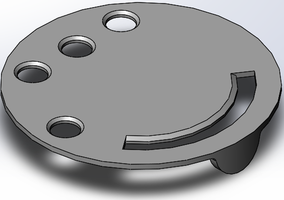
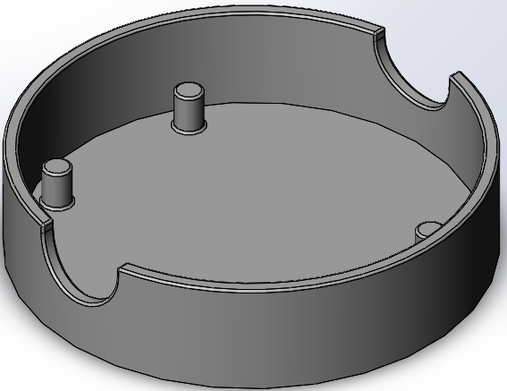
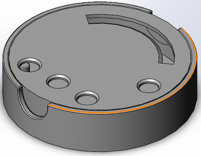
Most of the changes were done in the top part of the box. In version 0 the holes made in the side of the bottom parts are to put inside the fingers an pull to open de box. It is a problem because the top part can be broke. This is solved in the version 1, Where two fins are placed in the top part that fits with the holes in the bottom part. Then there are a stronger part to hold the top part and open the box. However the holes made in the top part for the LEDs are too small and the places for the knobs are so near each other that can not be moved. These error are corrected in version 2 cnaging the holes layount and modifying the overture for the LEDs. Also four cylidrical pieces are added in the bottom part to support the PCB.
Electronic Design.
The circuit can be splitted into three parts:
Filter
The filter is not fully design by myself. I took this design from the book "55 Ciruitos especiales de Baja Frecuencia".This is an active filter, is made with a one-stage basic amplifier which has a filtered feedback. The filter is implemented with a bipolar transistor, but I change it for an operational amplifier.
Amplification Stage:
This stage is implemented with one operational amplifier with an inverting configuration. Is importan to say that I use a single-supply, so I had to introduce an offset voltage in the non-inverting terminal.
Bar Driver:
I use the same circuits that are shown in the driver's datasheet, that is available in the likns that are at the end of these section.
Once the circuit was defined I started the simulations. The design is done with the software Altium, but the simulations were done with Proteus. Only the filter and amplifier stages has been simulated. This simulation is an AC sweep because we want to obtain the frequency response and the gain of the circuit. The Proteus proyect and the simulation results can be downloaded here:
There are two integrated circuits required: LM358 and LM3914.The LM358 is an integrated circuit with two operational amplifiers, one will be used in the filter and another will be used for the amplifier. The LM3914 is a dot/bar display driver that will be used with the LEDs to implement the LED bar. To capture the sound I use an electret microphone. This type of microphone ar very common in electronics that need to record any sound. The datasheets of all these parts are here:
PCB Design.
The PCB design has been condicioned by the mechanical design and, in the fisrt stages, by the LM3914 package that will be used. first PCB designs were done for a square PCB shape until the version 1 of the box, then the design changes to a round PCB. About the LM3914 package, the fists PCB designs were done with the PLCC20 package. However, The DIP-18 package is cheaper and it is not a high density design, so this was the final package option. After that the changes are due to changes in the holes layout in the mechanical design. Also a change in the place of the battery, to equilibrate te device, makes that the PBC has to be changed. The final version of the PCB is this:
The other PCB versions can be found here:
Proyect Libary (SCH+PCB+3D)
Altium allows to do a Integrated library with all the components that were used in the design. These can be done with the option Design >> Make Integrated Library.
In the next link can be downloaded the integrated library of these proyect. In these library there are the schematics simbols, PCB footprints and 3D models that have been used for each component:
3D Design.
Here we have the 3D design of the device:
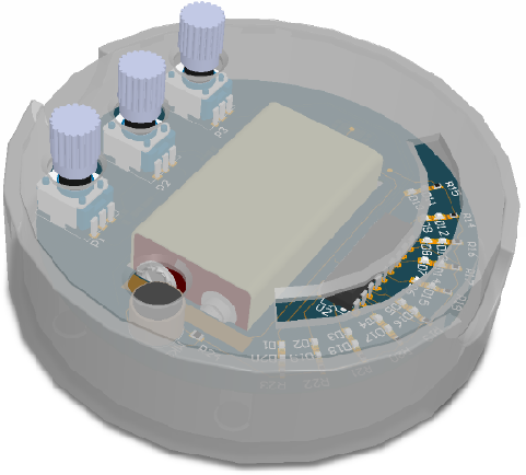
Now let's see the PCB and the Box separately:
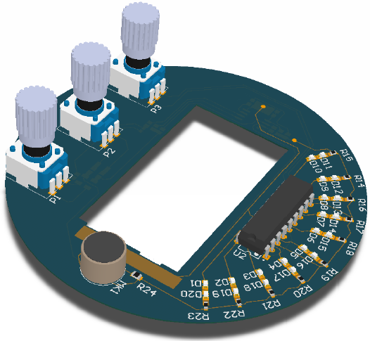
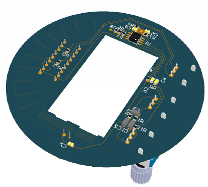
Design videos.
Here can be seen some videos made with altium and solidworks. These videos shows the final design for the PCB, the Box and the final assembly of them:
Providers.
The providers are www.rs-online.com and www.farnell.com. In these two web sites the components can be founded. In the BOM there are the link for each component.
About the 3D models for the electronical design, in the web page www.3dcontentcentral.com can be found all the needed models. To download the model is necesary to be registered in the page. Furthermore, In this link Altium libraries we can find a lot of free altium libraries. Is important to say that these libraries are not updated since the launch of Altium Designier 10.
Bill Of Materials (BOM).
Here can be seen the BOM.In the last column are the links to each product.
Proyect downloads
Here can be downloaded the altimum proyect and all the SolidWorks models:
Conclusions.
At the end of the proyect I came to some conclusions:
- Is very importan to schedule when each of the stages will be done, because it helps to save more time in the process.
- Clarify the reports that have to be needed and how they have to be done. If we do that when we do the schematics or PCB the things are done thinking how the reports have to be done.
- You have to know the PCB fabrication technology. It is an important thing to take into account when you ar designing the PCB due to it allows you to use multiple layer, for example. Also it is important in the package election.
- About the mechanical design, the material and the fabrication process is an important board condition. For example in this proyect the box was made of plastic and the manufaturing is done with a 3D printer. It has lamination problems that obligates you to add chamflers in the places where two sides make a 90º union, if you do not want that the box break into pieces.
Next improvements.
One of the improvements is to put a transparent plastic In the opening of the LED bar. A big amout of dust could come through this opening and it could be a future problem.
Valuation of the carried out work.
All the diferent issues that I have to manage in this design makes me realice that the electronic design not only involves the schematic and PCB design. There are a lot of board conditions to be managed. Also, the design process is not a continuous staged process. It has feedback loops that make the process harder. This proyect have not been complex, but it needs a lot of time. Mainly it is due to the learning process. I learnt a lot of things about professional design tool, but the learning process requires a lot of time. Furthermore, sometimes I had to repeat the work done in some stages due to It had not been done correctly. For example It happened with the schematics, I had to redo the schematics at least three times.
Also, in my case I had to do a design of the circuit because I do not start with a created proyect.However I did not do the complete design process because I search circuits that had already been designed and joined them to create the complete system. Here I had to use the knowledge adquired in next courses because I had to see each of the selected circuits and decide if I had to put anything to join all the circuits together.
Optional Proyect: Musical wheel
Objective:
This is an optional proyect wich consist in building a musical circuit. It has seven light sensors,with are implemented with a Light Dependent Resistor, and depending on the sensor that we cover the circuits reproduces a different musical note. More than one notes can be reproduced at the same time. One of the main singularity of this circuit is that it do not have substrate, the elements are connected by wires that are "in the air". It makes that in the design of the circuit we have to work with three dimensions.
These proyect is done by other seven students. One of us have to do an oscillator Whose main frecuency is a musical note frecuency, it does not matter if It generates a sine, square or triangular wave. In my case I have the frequency of the oscillator have to be 440Hz, witch corresponds with the "LA" note. The simulations of this circuit were done with Proteus. like in the proyect, because it allows to hear the output signal. The oscillator is implemented with a 555 timer. It is configurated to generate a triangular signal and I decided to use an output filter to eliminate high frequency components. Also I use an operational amplifier to decouple this circuit and the other stages, becasue an amplification stage is needed to have an audible signal. I had a LM358 operational amplifier, wich is an IC with two operational amplifiers, so I use another operational aplifier between the oscillator and the filter. The proyect can be downloaded here:
After these the circuit has been implemented in a Protoboard to test it with real component. Here there are a video with the result of the tests, it may be necessesary to rise the volume control:
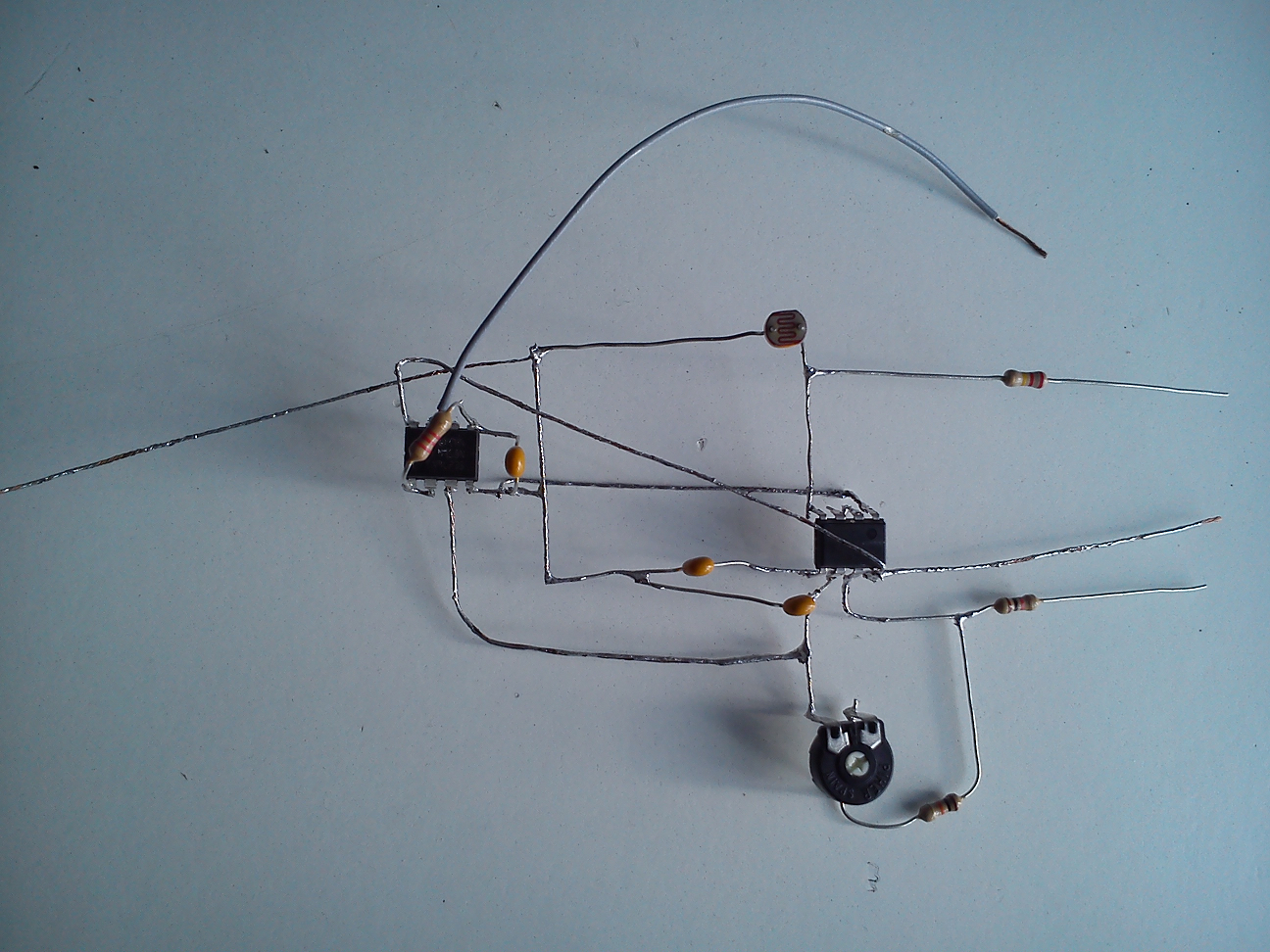
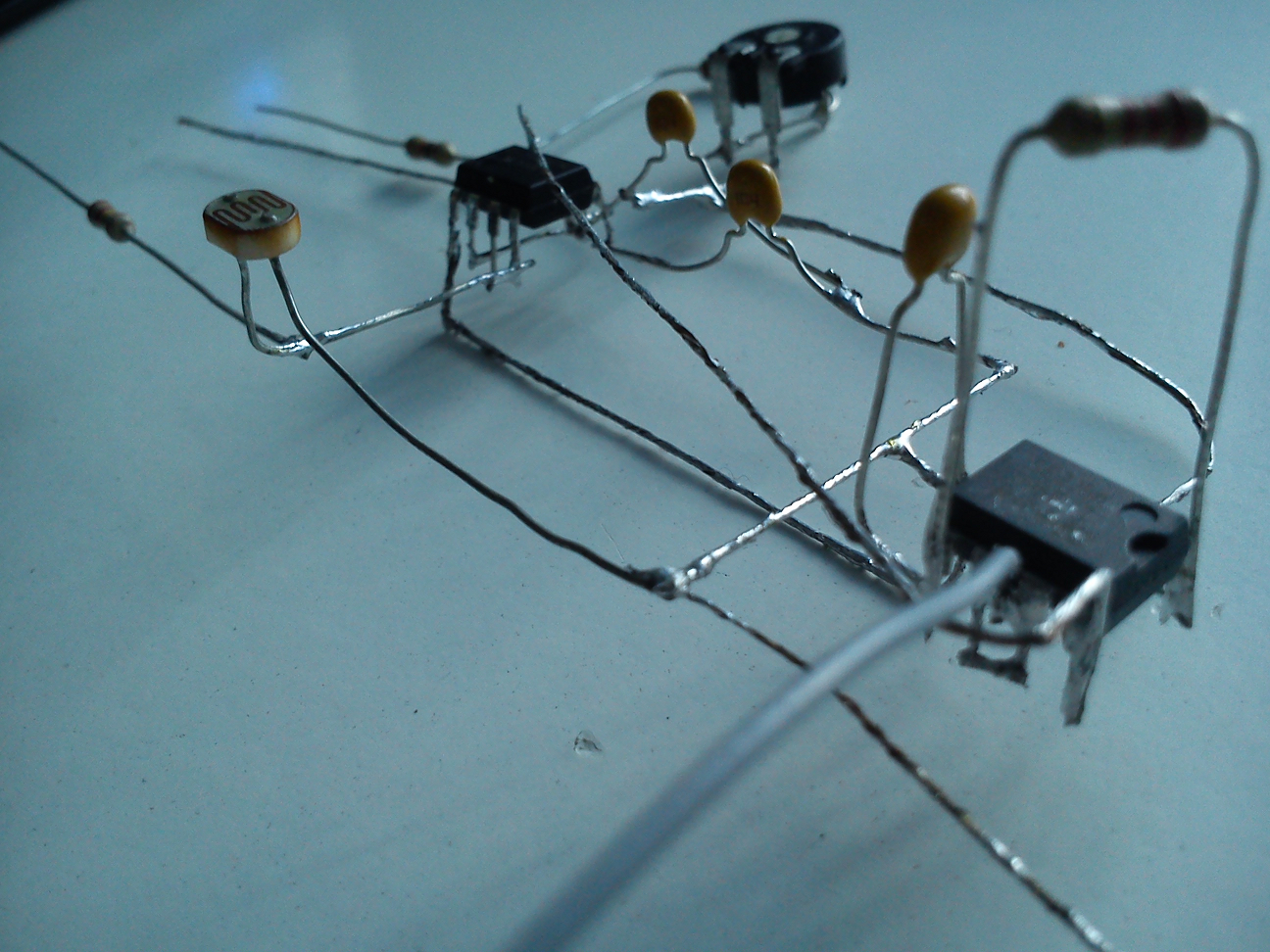
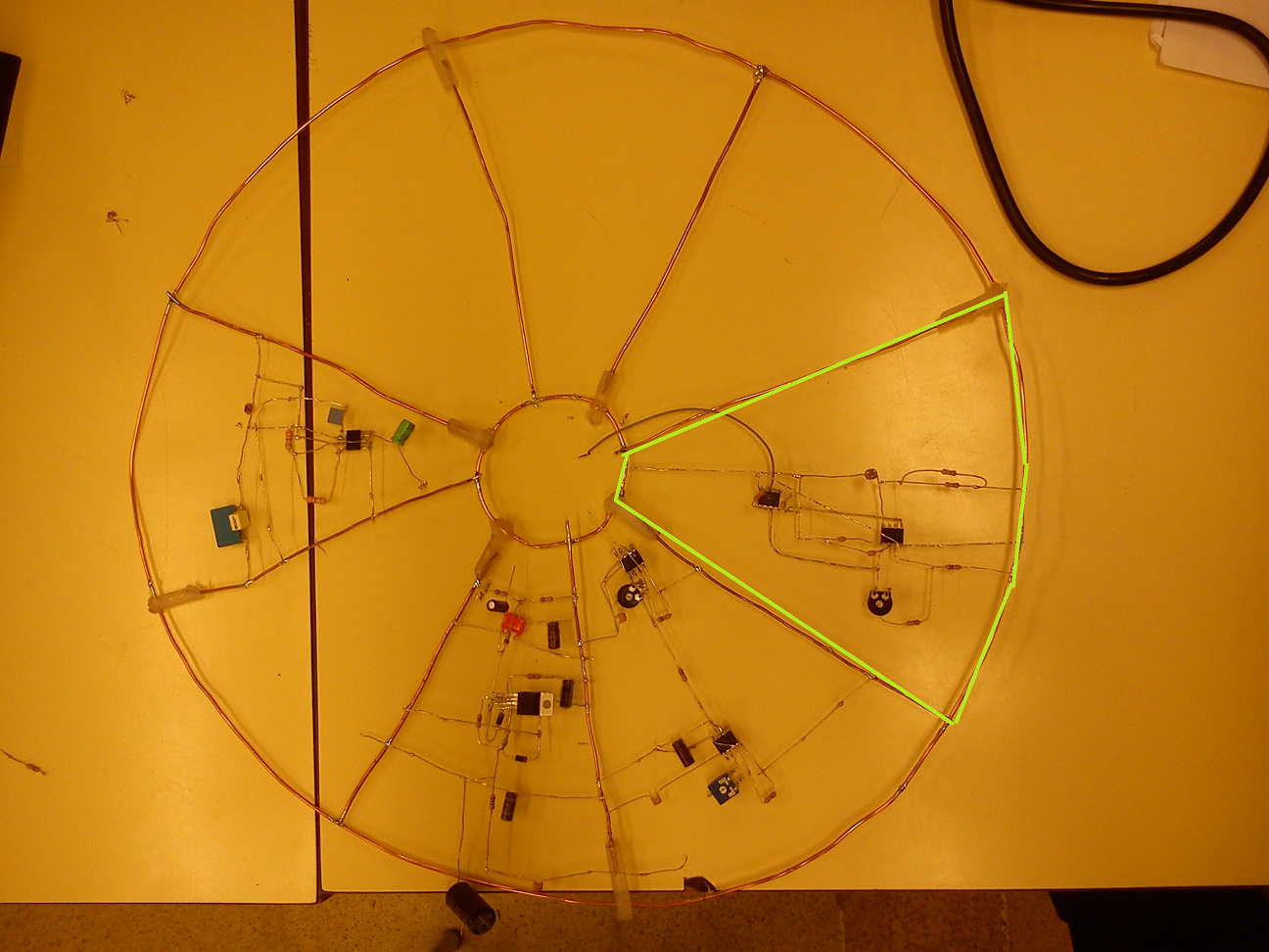
Once the circuit is tested the next step is to solder all the components and join it with the other circuits. The following pictures shows the soldered circuit and the circuit in the wheel:
