Claxon
María Armenteros Fernández
(mariaarmenteros@correo.ugr.es)
Printed Circuit Technology

Laboratory activities.
Desoldering techniques by hot air gun
One of the tools for desolder components is the hot air gun. It is useful for surface mount components because surface mount chips are especially hard to desolder because it's very difficult to completely remove all the solder pin by pin, and avoid overheating the board and lifting a pad.
Some tips that helped to me are:
1. Wait for the tool is hot (about 350-400 degrees).
2. Be careful, because the tool throw out air constantly.
3. Wait for the component is hot because when it is ready, it will be desoldering really easy.
Desoldering techniques by gun
It is used for desoldering trough hole components. It heats the tin of the lead and absorb it.
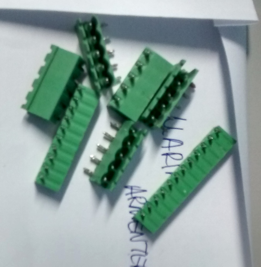
In the next pictures you can see the components I unsoldered.

SMD Welding techniques by soldering iron
1. Place a thin layer of tin which will perform welding.
2. Put the component at the point of contact with tin and set up.
3. Set up the tin with the other side the component.
Recognition of elements in a PCB
In the next pictures I am going to recognize some elements of a real pcb
Integrated project.
Project objectives
For this project, I want to do something funny, so I decided to do a claxon, but not a normal claxon, I did a special claxon. This musical horn that in addition to I having a sound clearly nicer than a single ring , will be rotated generally passersby with a large smile on his face
You can dowloand the pdf where I found my idea.
Design Stages
1. Choose the device
2. Simulate the circuite
3. Create the box
4. Create the Altium project
5. Check the correct prototipe of PCB
6. Check complete assembly
You can see the hole diagram - here
Mechanical Design
This part was my favourite. We used Solidworks to design our box and at first, it was very difficult, but after I used a few hours, I understood it and it was easier.
You can see the box with it dimension in the next picture:
I edit two videos, one is only of the box and the second is an assembly of PCB and the box.
Another tool of Solidworks is that calculate the center of mass. You can see the center of mass of my device - here
- Click here if you want to download the box with the PCB assembly
Electronic Design
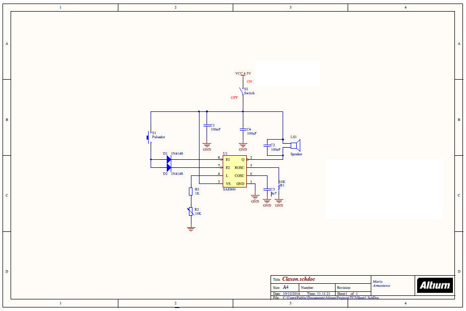
In the next picture you can see the schematics of my device:

As you can see, the circuit is easy. Anyway, I'm going to explain it. The circuit works because of SAE800. It is an old integrate circuit that doing "gogns". This integrate, like you can see in the datasheet, works between 2.8V and 18V. For this reason, I "feed" it with three batteries AAA. The switch 1 is only necessary if you want to do make the battery last as long as possible . in Indeed, when the circuit is not activated, is I mean, while not acting on the button S2 , automatically switches to standby and consumes only a small uA .
Datasheets of the components I used:
Library
It is very important to have a very complete Altium library and it has to have the PCB library and the SCH library.
You can download my libraries in the next links:
PCB Design
When I started this project, I don't know nothing about Altium. So, the first I did was place the basic components like reistances or capacitors. After that, I look for my others components on the Internet. If you don't find your component, you have to design it. I was lucky, so I didn't have to design any component. After that, you have to look for the footprints of your components. If you don't find the exacty footprint, you can use one similar.
When our components are positioned, we have to routing them.
My finally PCB:
3D Design
I include some photos and videos of my 3D PCB.
BOM
Bill of materials .
You can download the excel with the providers and links where I bought the componentes.
And -here is the PDF with the hours I worked and the total budget.
Real photographs of the project
Futures improvement
I think I can improve my device if I reduce the PCB and then, the box. It will reduce cost and space, the two essential for a good job.
Assessment work
I think this subject is for student who has time, because it require a lot of time. But, if you have it, it is one of the best subject because I learnt a lot and I had a goot time learning, that it is very important too. Furthermore, we went visited 3 real business and they taught us many important things.