Printed Circuit Technology
Course Report
Contact Information
1. Laboratory
Desoldering and Soldering techniques
During the course we have learned to use techniques of soldering and desoldering. In the next picture you can see I desoldering SMD components using hot air:
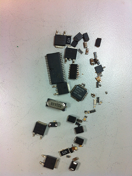
In the picture you can see different SMD components: SOP, QFP, SOT, etc. These components were desoldered with a temperature around 380ºC
I have also used desoldering tool of soldering station to desolder relays:
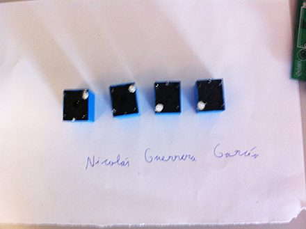
We have also soldier SMD components using welder. In the next video I go welded one SMD resistor:
Recognition of elements in a PCB
This panel has four pcb and is manufactured by: Sogecam Industrial

The PCB are poorly signposted, it has no information of the components, so I used reverse engineering to try to guess the components of the PCB.
Top

Bottom

-Bottom
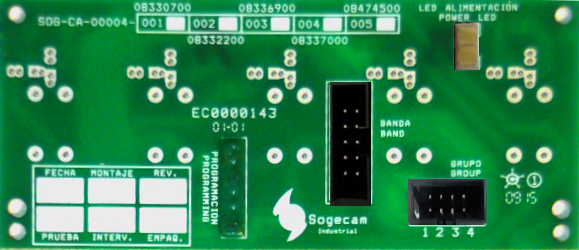
Looking at the pcb can be easily identified ground plane. The power line can be found if you look at the top layer, because there is an text that says "power led" so it must have 1 pin for ground and power pin. Looking at the bottom of the pcb see power line.
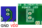
We can follow the line and see that the line is cut at a point where a component should go.
This component is probably or a protection diode or a fuse to protect the circuit, since then the line goes to the integrated circuit power there
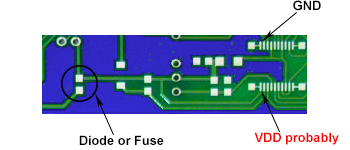
As I said if the line continues we see that the line goes to an integrated and again the line is cut by another component. If you look at this component passes below the ground plane so that the component may be a 0 ohm resistor to act as bridge.

Finally the ground plane and the power line would be as shown in the following image: (blue = ground plane, red = power line):
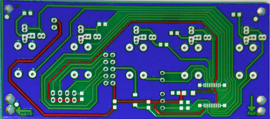
On the top we see that there are pins that are called programming. Then it is probably that they are to program the integrated circuit that should be on the bottom.
We see that the tracks go to a pins of the integrated circuit. If we see the pins of programming a microcontroller pic of 20 pins, we see that go to the same pins.
So I can say that the integrated circuit is a microcontroller:
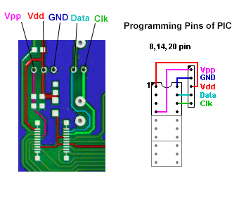
If we know this, we can guess other nearby components such as:
Resistance that should go between Vdd and Vpp for programming. And a capacitor (bypass) that should go between the power and ground.
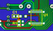
In the next picture we can see a line in orange corresponding to a signal from the microcontroller goes to a pin of a connector. But the road is cut by a component. This component may be a diode or resistance or bridge 0 ohms.
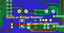
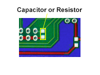
There is a component that is to the left of the diode / fuse can be either a resistor or capacitor:
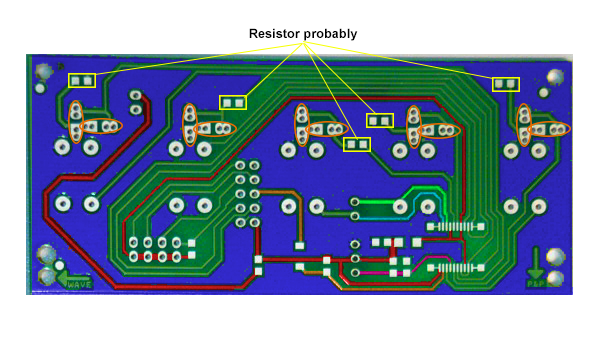
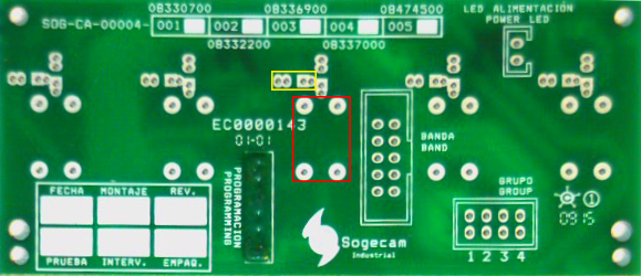
The smd components that remain to be identified are those listed in yellow in the image below. We can see that these components are in series with 2 through-hole components that are parallel (surrounded in orange). All these smd components are grounded but one that is between the through-holes components and signal pin of the microcontroller. So it is possible that these components are resistors (not sure).
After this analysis we finally have components that could go in the bottom layer would be:
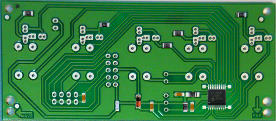
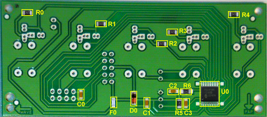
-TOP
There are two types of components through-holes in the TOP layer without connectors.
I do not know which components could be.
Both are 4-pin, the smallest SIP has to be packaged.
The SIP packaging is marked in yellow and are 10 in total. The other is framed in red and there are 5.
• Connectors
-Power LED:
2-pin IDC
-Group
The connector type may be male 8-pin IDC
-Band
The connector is a 10 pin IDC male
-Programming
I do not know which connector could be.
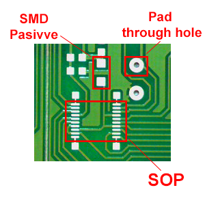
-Types of pads
You can see that there are SMD pads of pasive components, SOP (microcontroller) and pads for through hole components.
2. Project: Color2Music

This project was made entirely from 0, so that the work has been difficult due to time available. The idea is to own. I created from 0: Both the circuit design, as the program the microcontroller, like libraries that control sensor, as the library for generating sounds, such as housing design, such as the design of the PCB,etc. Everything has been done in the 1st semester of academic year 2014/2015.
All software, pcb, schematics and 3D models of the box can be downloaded and freely modify https://github.com/nitehack/Color2Music under GNU license

What is Color2Music?
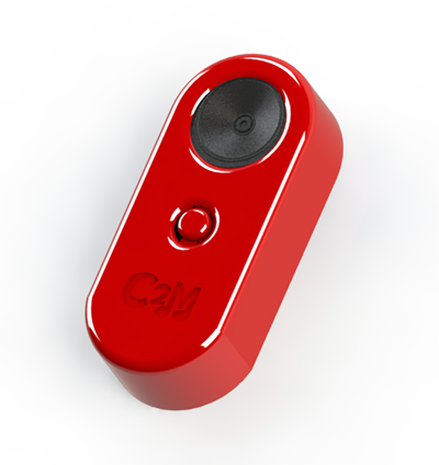
Color2Music is a device whose purpose is to transform musical notes colors in order to create a new way of making music.
Using Color2Music
To use it enough to support the Color2Music by the sensor area on a surface and push the button.
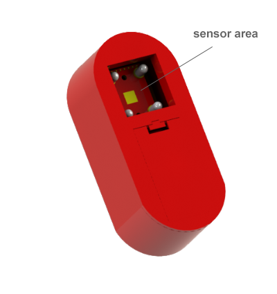
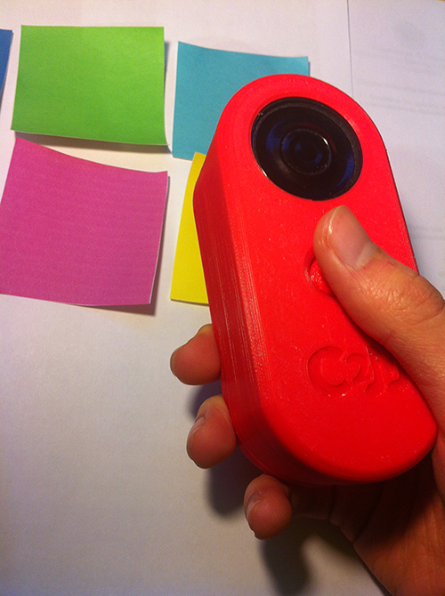
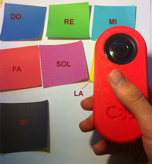
The "color-> musical note" correspondence is:
Blue-> Do
Green-> Re
Cian-> Mi
Red-> Fa
Magenta> Sol
Yellow-> La
Black> Si
Operation
Color2Music colors detected by the color sensor TCS3200 and the microcontroller PIC 16F88 the "color-> musical note" conversion is done.
The procedure is as follows:
The color sensor is activated by a pin and returns the light intensity of the three basic colors by changing the frequency of a square wave. In the microcontroller these frequencies are read and the color is identified with the note that is to be generated. By CCP module generates a PWM signal with the frequency of the musical note that corresponds to the read color. This signal is directed to a speaker.
Project Stages
This project has been both hardware, software, and design. The scheme of project stages is as follows (although I havent followed strictly this scheme and could be better):
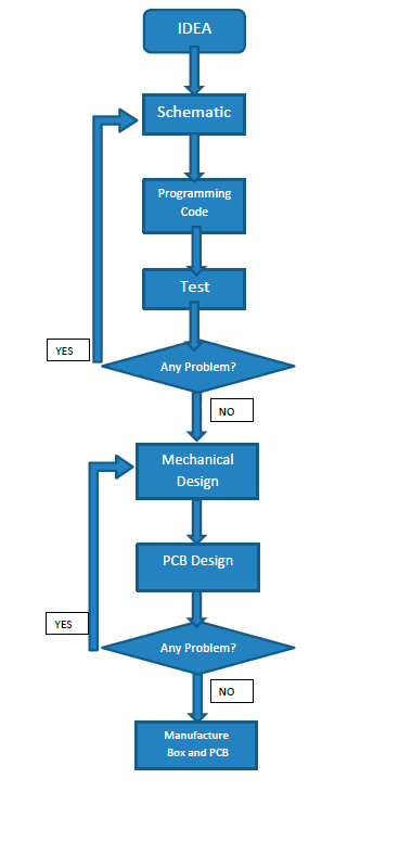
I have to clarify that in my project simulation was difficult because I didn't have the simulation model of the color sensor, so I've done the test on a breadboard physically
Hardware
Mechanical Design.
This is the design Color2Music box.

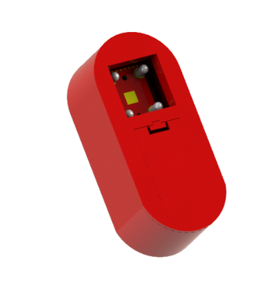
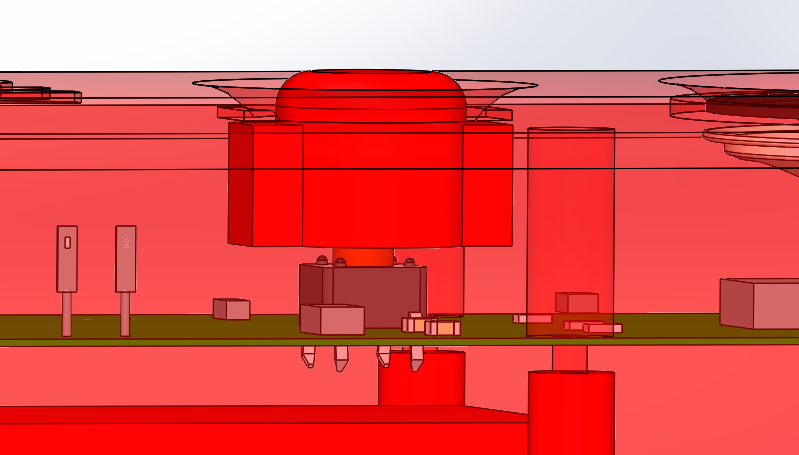
This box has 4 pieces: Upper part, Lower part, Front, Button.
-Upper part:
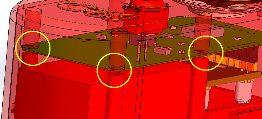
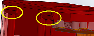
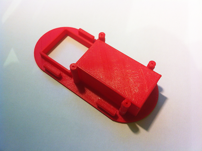
This piece has two holes, one big for the speaker and one little for which the button is introduced. Has within four pivot pins with some little at the end. This is to hold the PCB without having motion and thus save screws. In the larger hole is a grip to hold the speaker in a crescent shape. At the top there are slits to connect the bottom part with the top
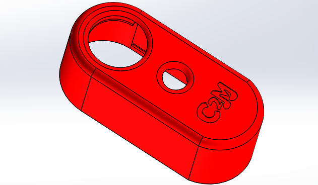
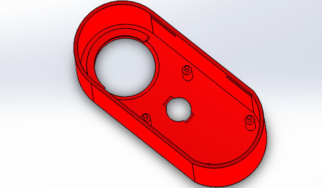
Download Upper part
-Lower part:
The lower part has a square-shaped hole through which the color sensor can detect the colors. Also the lower part has a small box that has a 9V battery There are four pivots to grab the pcb as explained before, and also has four latches to raise the upper part and the lower part.
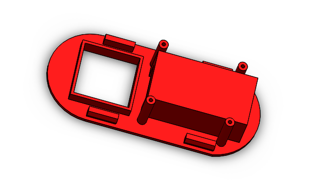
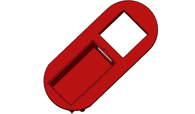
Download Lower part
-Lid:
This piece I designed noticing a box of an electronic device that had a lid.
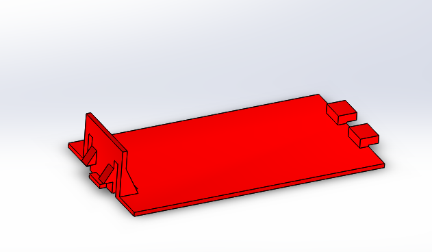
Download Lid
-Button:
To turn Color2Music
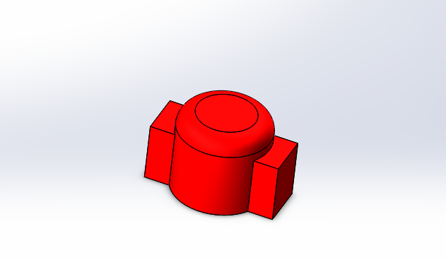
Download Button
-Center of gravity
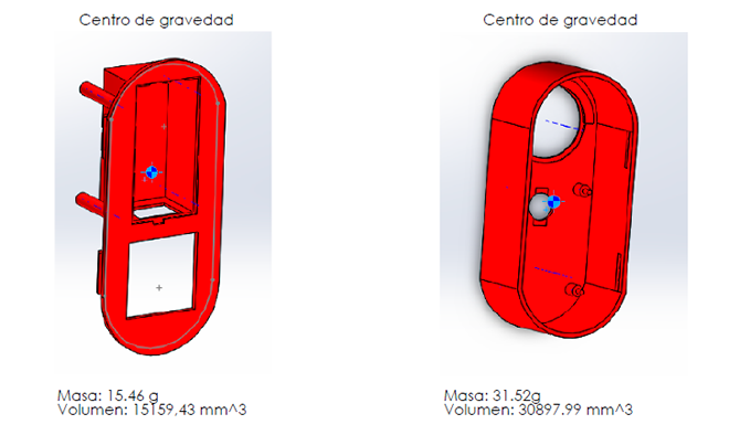
The center of gravity of the housing is as follows.
This symbol indicates the center of gravity

-Inside

-Holding the pcb
-Connecting the two shells
-Connection button
-Assembly
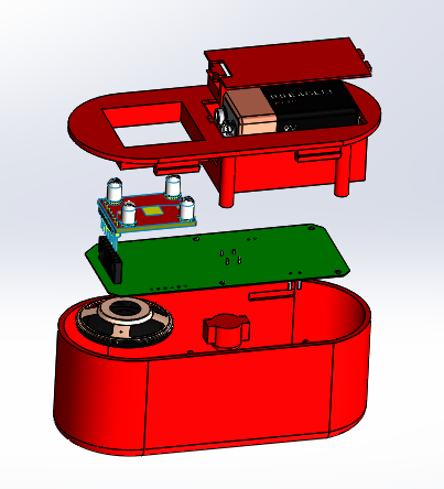
Download Assembly
In the following video you can see a sample of the mechanics of Color2Music
-Planes can be downloaded from:
Electronic Design
The circuit consists of 6 areas:

-Sound:
This circuit consists of a speaker a 2N2222 transistor and a resistor. A transistor because the pic can give a maximum of 20 mA per pin is placed, and speaker consume no more than 625 mA in the worst case.
Datasheet: 2N2222
-Control:
The control region has a microcontroller PIC 16F88, a capacitor and a resistance of 10 K between VCC and MCLR. The microcontroller is responsible for controlling the color sensor, to control the RGB LED and generate the appropriate frequency wave to generate the musical note. The capacitor is between power and ground is a bypass capacitor. (In the circuit of the PCB will see that is placed very close to the pins of the PIC, to fulfill its function well) The 10K resistor is a resistor pull up to use the VPP pin and MCLR programming.
Datashet: PIC16F88
-Sensor Color:
This area has a connector 8-pin female header. The sensor is detecting the colors and tell the PIC that color is. This sensor explain how it works in the Software section.
Datashet: TCS3200
-Programming:
This zone Includes 6-pin header to program the microcontroller once assembled PCB and to make future updates.
-Supply
For power I used a LM7805 the two capacitors, a connector for connecting the battery.
It may seem odd to see the button between the controller output power to the circuit. Why not put a switch? Because the color sensor is poorly designed and can not control some leds which has around him, to measure the brightness. So if a switch in ON, would always be lit LEDs, so we would be spending unnecessarily mA. The solution has been put down for the pic do its function (convert colors to a musical note) when you get the power.
-Color Indicator:
This area is an RGB LED and 3 resistors. The rgb led inside has 3 leds common anode. The resistors are current limiting.
Datasheet: LED RGB
PCB
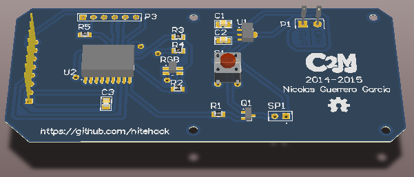
For PCB has tried to find the maximum number of SMD components.
It has elements of different areas as close as possible to distinguish easily.
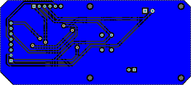
This PCB has two layers. The bottom layer is the connector of the color sensor and the top layer are other elements.
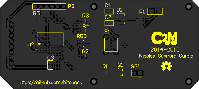
You can see it has been included in the PCB which I have included in the top layer overlay the logo of the product and other interesting information.

PCB TOP
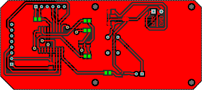
PCB BOTTOM
PCB TOP OVERLAY
Circuit elements
Build of material of Color2Music can be downloaded from:
-PCB can be downloaded from:
-Schematics can be downloaded from:
-Planes can be downloaded from:
Software and Analysis
Color Sensor
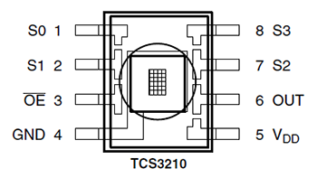
The sensor is able to detect the brightness of the three basic colors (red, green, and blue). The sensor has a 4x6 matrix photodiodes: 6 photodiodes with red filter, 6 photodiodes with green filter, 6 photodiodes with blue filter and 6 unfiltered photodiodes. Within this sensor has A/D converters to read the analog signal from the photodiode.
-How work Color Sensor?
The frequency range in which you want to work with S0 and S1 pins and the filter you want to use with the S2 and S3 pin is selected is selected. Pin "OE" is set low to leave a square wave at a particular frequency that indicates the intensity of the color.

-Frequency measurement of the color sensor
To measure the frequency, I start a timer of the microcontroller when a change occurs in the RB0 pin (the pin that is connected to the output of the sensor) and it reads value when a rising edge appears. With this value its knowing the frequency of the internal clock can be calculate the frequency of the square wave that reaches it. The problem of measuring the frequency is that the error is formed increases with increasing frequency. The range of frecuency that I have chosen it is 12 KHz, after making the respective simulations I have seen that the error it was small.
The library I have made to do this can be found at:
-My repository: frequency.c
-Sensor Calibration
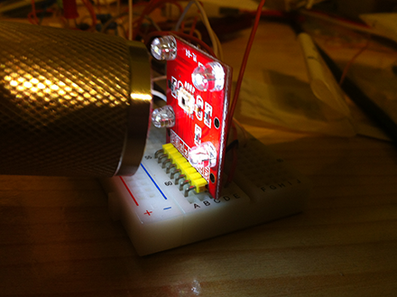
Keep in mind that the sensor is not perfect and when the maximum brightness photodiodes of the 3 filters will not give the same output. So I had to be adjusted by software setting zero and gain.
For the zero setting I have activated all 3 filters one by one and see its output by the sensor receives nothing or no light.
To gain I focused white light sensor and have listed the values the sensor gives and have adjusted the three maximum theoretical value.
-Study of colors and methods to detect
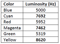
Although the sensor can measure any color, when assigning "colors-> musical note" I have chosen primary colors with basic mixtures: red, green, blue, cyan, magenta, yellow. To recognize colors I have done an experiment with colors printed on one sheet and I measured the response it gave each of the filters:
Keep in mind that the resolution that I have chosen for the sensor rate is low then the resolution is low, but remember that it is the best choice to get the lowest possible measurement error of frequency.
If we correspondence bit RGB primary color theory and mixtures thereof (value 1 the maximum frequency and value 0 the minimum "theoretically") ("R" 1º bit, "G" 2º bit, "B" 3º bit):
-Black 000
-Blue 001
-Green 010
-Cyan 011
-Red 100
-Magenta 101
-Yellow 110
-White 111
We see that in the previous graphs that when the frequency value must be maximum we obtain a value slightly lower, and when should be minimal we obtain a value a little higher or a lot more.
One of the causes of potential errors due to the measure are: the ambient light and printer colors are not exactly the color that they should be.
To recognize these 6 colors I tried to put a frequency level to decide if bit color was either a "0" or "1", but there were problems. Later I opted for a method using both photodiodes filtered and unfiltered photodiodes. As the objective is to generate music from the colors that are listed earlier in this section, I noticed that the mixture of primary colors reflect more light than unmixed each separately. So I have used this to recognize the mixtures.
The library I have made to do this can be found at:
-My repository: color.c
Generation of musical notes
For the generation of musical notes, I had in mind the limitations of the microcontroller (the size of the timers) and clock frequency (it must be such as to not affect much to the reading of the frequency of colors used to detect color and that it could generate the greatest number of frequencies within the audible range) In order to generate musical notes a square wave is generated by a CCP module with a duty of 50% to the desired frequency. This PWM signal passes through a speaker generating an audible tone.
In software I have saved the possible values to generate the musical scale. Frequencies are:

The library I have made to do this can be found at:
-My repository: sound.c
Manufacture and assembly.
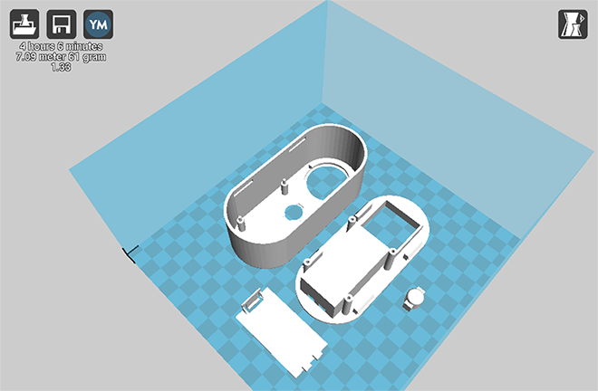
-3D printing using Prusa i2

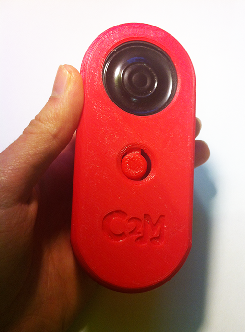
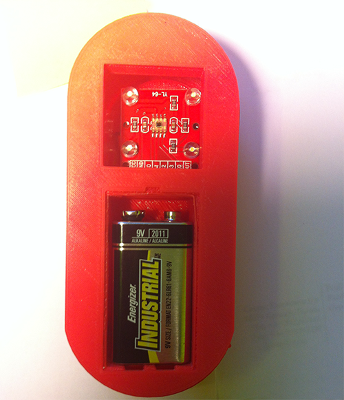
Color2Music running...
Testing detection of basic colors
Testing Color->Music
♫ ♫Happy birthday to you ♫ ♫....
Conclusions.
In conclusion with good planning from the start can make a good product. First simulations must be carried out (in my case could not because there is no color sensor simulator) and debug the design in simulation until the final circuit. After spending the concept of the box and the PCB layout. There are many ideas that have occurred to me along the way that could not be included due to time constraints. In paragraph improvements are explained.
Future improvements.
The improvements you would make to Color2Music are:
-Make a smaller box
-Sound filtering
-Lighting the periphery of the speaker when a color is detected (with color light detected)
-Use different color sensor that controlled LEDs or make my own sensor board
Personal Assessment.
For this project were applied knowledge of many subjects. I can highlight the following subjects: Circuit Analysis, Electronic Instrumentation, Digital Electronic Systems, Supply Systems, Power Electronics and Programming Fundamentals. A project like mine should be between two people, since it is a large workload for the time that is available. As said earlier, the project has been made from an idea that occurred to me, so I had to do everything from 0. I have been "software engineer", "hardware engineer" and "Designer" while in this project.
In relation to the subject, in my opinion this subject should be given in an entire year and not in a semester. I think it should have in the subject over 1 seminar to learn how to use Altium programs and SolidWorks. I say this because much time is wasted in learning watching tutorials, and sometimes can take hours and hours to fix simple things ... I also think that could be used for subject teaching as a platform SWAD. Since so everything would be neater and more unified (such as messages, activities, materials, etc). Although this is a matter of taste.
In my case the subject was the instructor of 3D printers.
I change the extruder of lab 3d printer (Prusa i2) and I corrected the faults that had mounting and calibrated.
However it still has some little bugs.
All these failures with the 3d printer could have been avoided had made a correct assembly.
As a final assessment I can say that is the subject in which I had to apply a lot of knowledge throughout the college career and is also the subject that most have had to work the whole college career.