| How to create a basic component with PADS Logic | |||
| Français | |||
|
Welcome to LIBedit-technologies Training Session 01. We will see together how to create a component with PADS Logic. To start, we will create the CAP-CC05 capacitor, a basic component. | |||
|
| |||
|
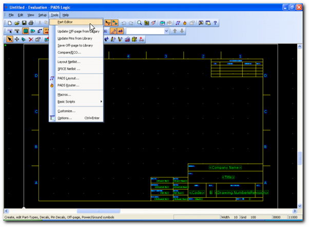
From the PADS Logic main menu select [ Tools ] and [ Part Editor ] commands...
| |||
|
| |||
|
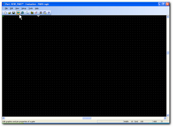
Now you are in the Part Editor. In PADS Logic you can create the symbol and the Part. To create the symbol click on the [ Edit Gate Decal ] icon...
| |||
|
| |||
|
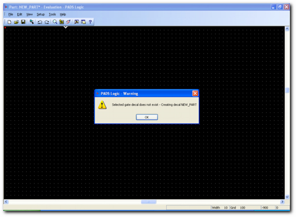
Click on the [ OK ] button to continue...
| |||
|
| |||
|
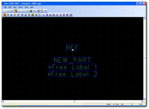
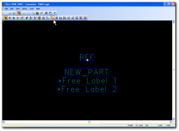
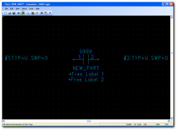
In the Edit Gate Decal window of the Part Editor, PADS Logic displays first some textfields and the origin of the symbol. REF displays the location of the Ref-Des (C1). NEW_PART displays the location of the component name (CAP-CC05). "*Free labels" displays the location of any attributes you may choose (Value for example).
| |||
|
| |||
|
Now we add pins (called "terminals" in PADS). In the PADS Logic main toolbar select the [ Add Terminal ] icon.
| |||
|
| |||
|
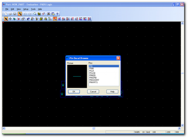
In this dialog box select the terminal type you want. For our example, we select the "PIN" terminal type...
| |||
|
| |||
|
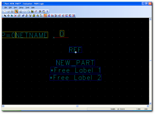
Move the cursor and select the location of the terminal. The mouse point is the connection point of the terminal.
| |||
|
| |||
|
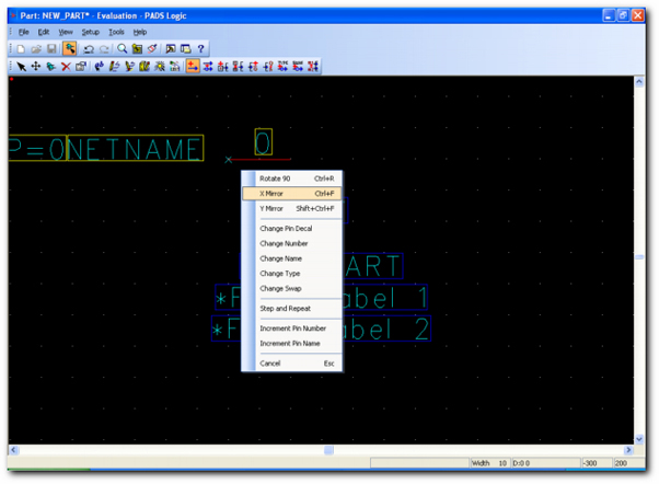
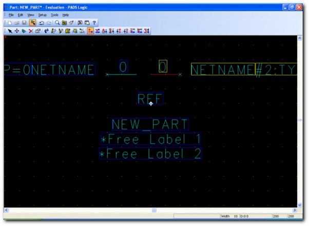
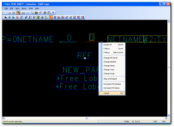
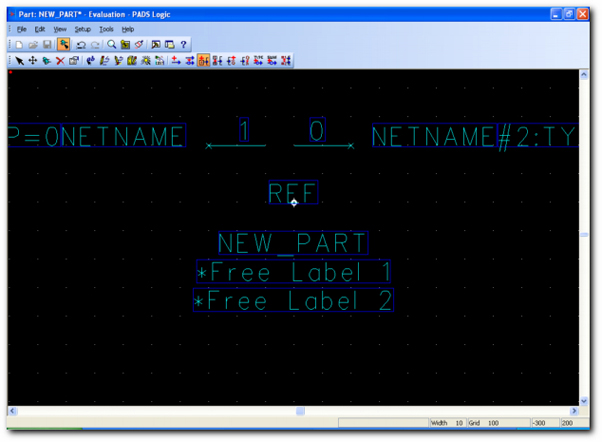
OK, we placed the first terminal. For the second one, we must mirror it before place it. Click on the right mouse button to display terminal options popup menu. Select the [ X Mirror ] command...
| |||
|
| |||
|
...and choice the location of the second terminal.
| |||
|
| |||
|
We have no other terminal to add. To stop this action select the right mouse button then select the [ Cancel ] command...
| |||
|
| |||
|
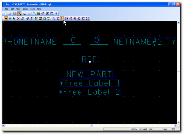
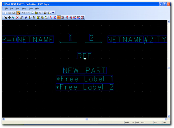
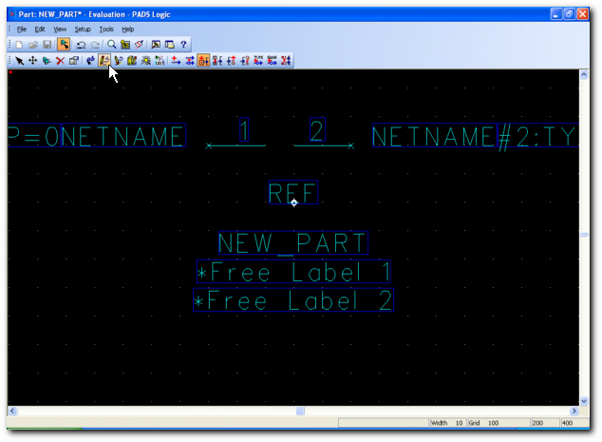
The next step is to set the pin numbers. In the main toolbar select the [ Set Pin Number ] icon...
| |||
|
| |||
|
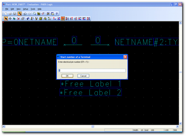
Enter the first number. Click on the [ OK ] button.
| |||
|
| |||
|
Click on each terminal...
| |||
|
| |||
|
PADS Logic increases automatically the Pin Number...
| |||
|
| |||
|
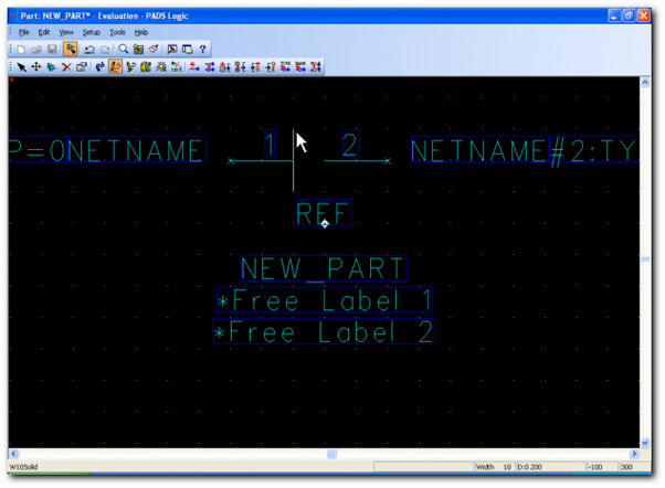
The next step consists to draw the symbol outline. In the main toolbar select the [ Create 2D Line ] icon...
| |||
|
| |||
|
With the mouse click on each point of the line. Complete with a double click.
| |||
|
| |||
|
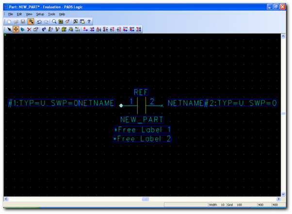
The drawing is done.
| |||
|
| |||
|
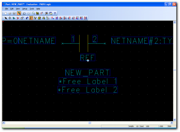
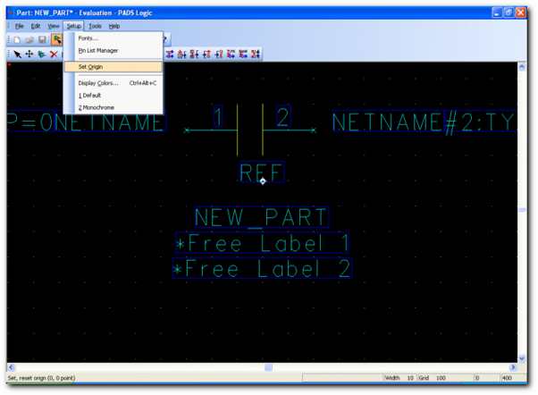
We must select the origin of the symbol. From the main menu select [ Setup ] and [ Set Origin ] commands...
| |||
|
| |||
|
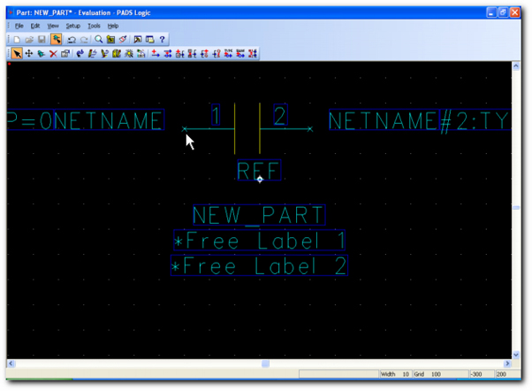
With the left mouse button, click on the new location. When you will add this symbol in a schema the component will be attached to this point.
| |||
|
| |||
|
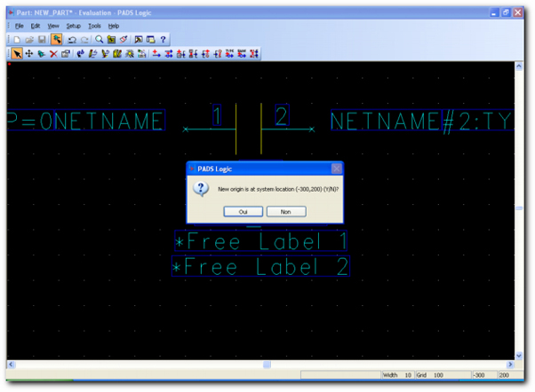
Confirm this action by click on the [ Yes ] button.
| |||
|
| |||
|
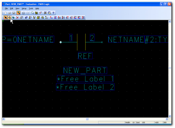
Now we will move all texts around the symbol. From the main menu select the [ Move ] icon...
| |||
|
| |||
|
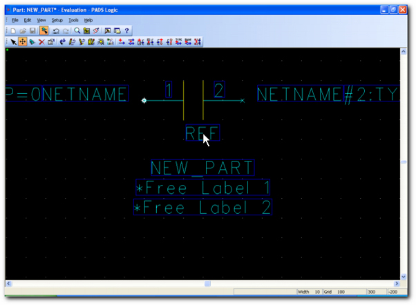
Click on the text and...
| |||
|
| |||
|
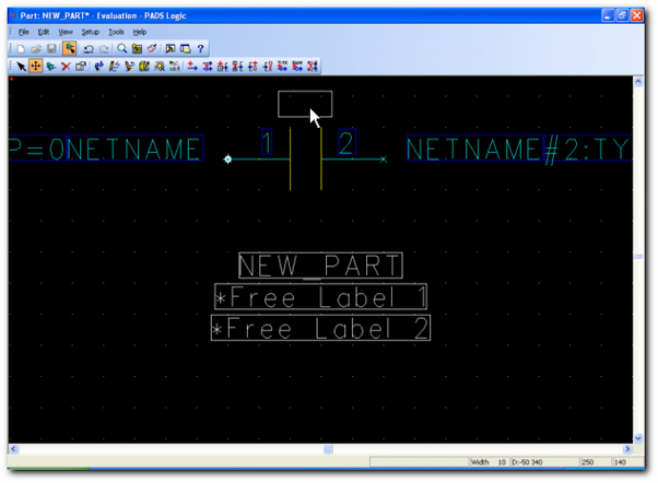
...move it to its new location.
| |||
|
| |||
|
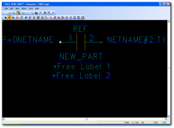
Done !
| |||
|
| |||
|
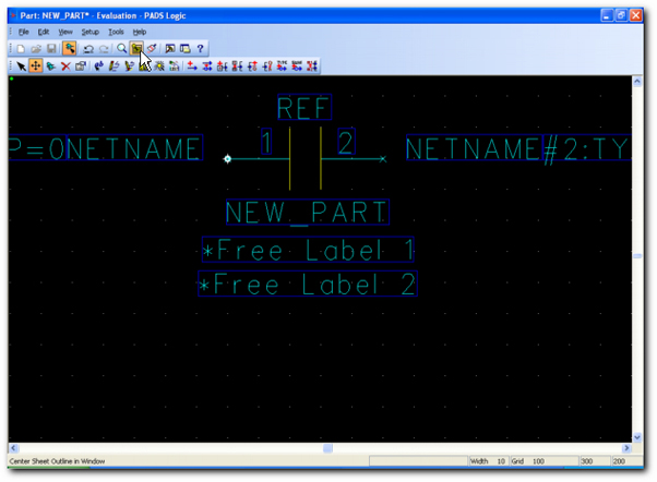
Click on the icon below to see all.
| |||
|
| |||
|
This command displays all drawings in the screen.
| |||
|
| |||
|
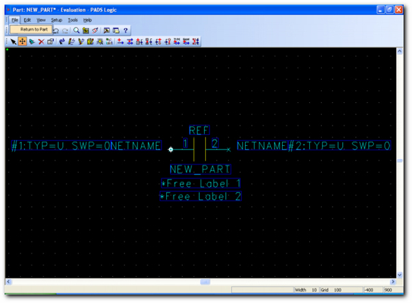
The symbol is complete. We can leave the Edit Gate Decal window. Select [ File ] then [ Return to Part ] commands...
| |||
|
| |||
|
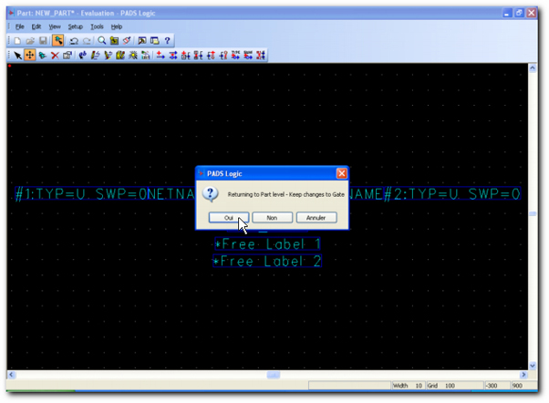
Click on the [ Yes ] button...
| |||
|
| |||
|
Now we will create the Part. When you add a component in a schema you add a Part.
| |||
|
| |||
|
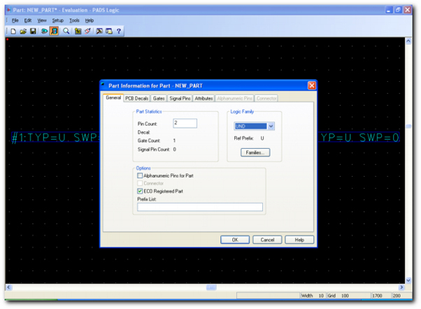
In this dialog box we will enter some informations...
| |||
|
| |||
|
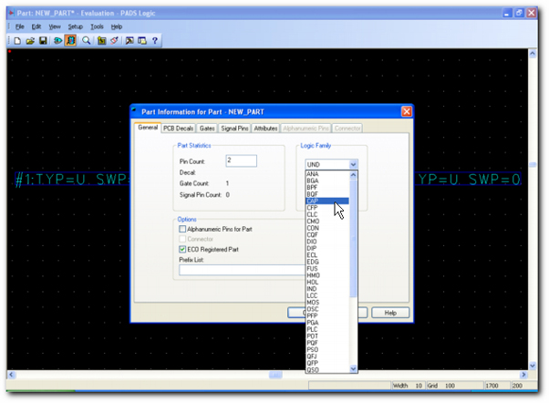
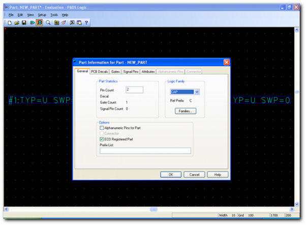
In the "Logic Family" section, select the "CAP" family.
| |||
|
| |||
|
This action associates the "C" prefix to the ref-des. When you will add this component in a schema, PADS Logic will place automatically the "C" ref-des prefix and the next ref-des free number in this logic family.
| |||
|
| |||
|
Now we will select the associated footprint. Select the "PCB Decals" section...
| |||
|
| |||
|
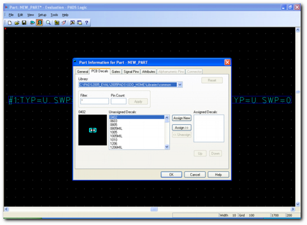
In this section you must select the library you want and the PCB Decal...
| |||
|
| |||
|
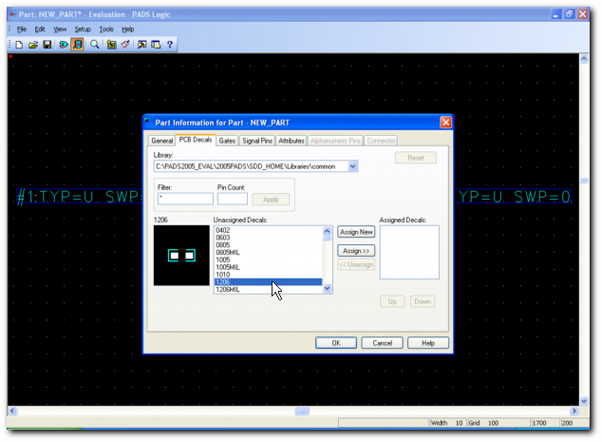
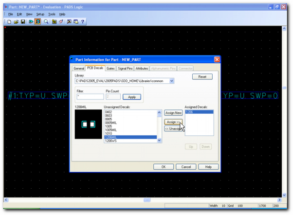
Click on the PCB Decal name in the "Unassigned Decals:" list. PADS Logic displays a Decal preview. When you find the good Decal click on the [ Assign >> ] button.
| |||
|
| |||
|
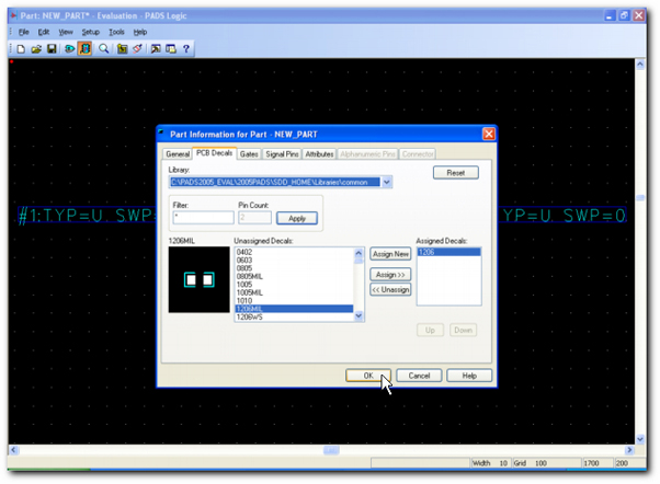
When you will import the netlist in PADS Layout, this Decal will be automatically added in the printed circuit board. It is possible to select other informations like attributes. But the goal of this first lesson is to learn the basic concepts of the component creation.
| |||
|
| |||
|
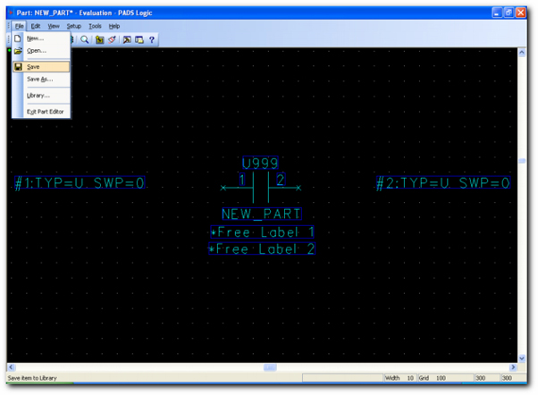
To save all select [ File ] and [ Save ] commands...
| |||
|
| |||
|
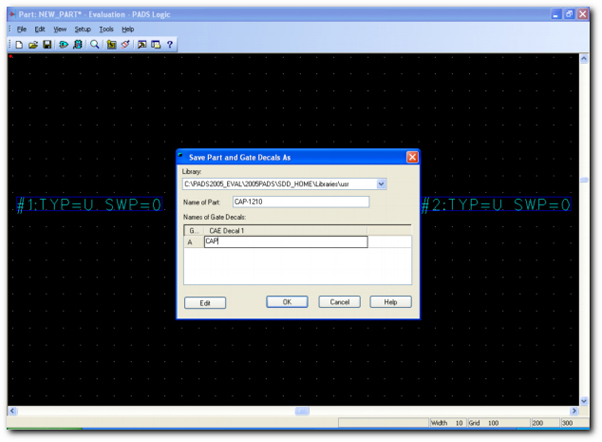
Enter the "Name of Part:" and the "Names of Gate Decals:". Click on the [ OK ] Button. The component is saved in the selected library.
| |||
|
| |||
|
| |||
