 CanSat
Integrated Project Based on ESA (European Space Agency)
Exploded View
Previous Designs
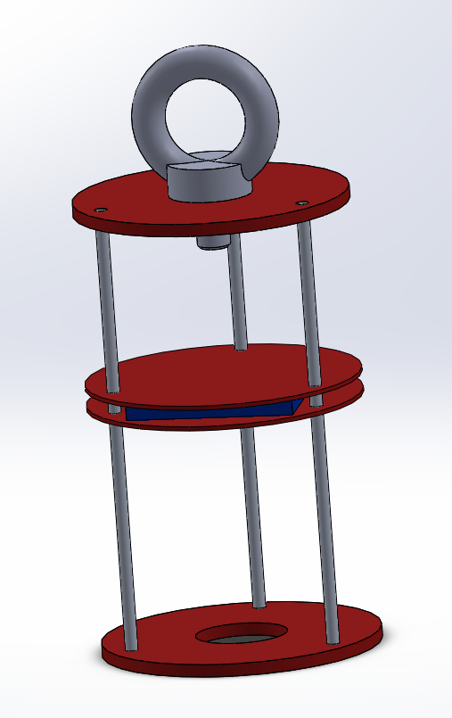
3D Solidworks Model

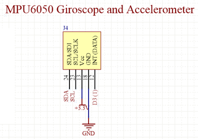
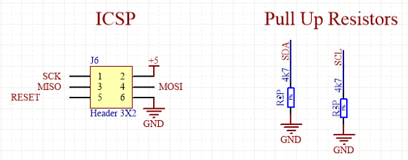
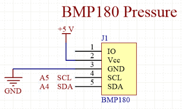
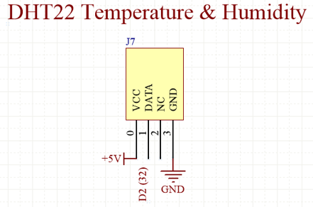
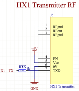
Schematics
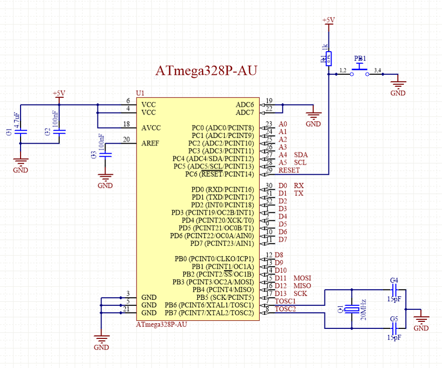
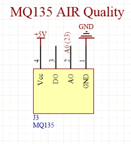
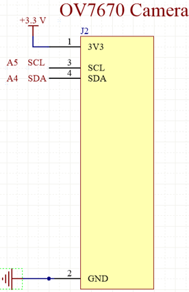

3D Altium PCBs
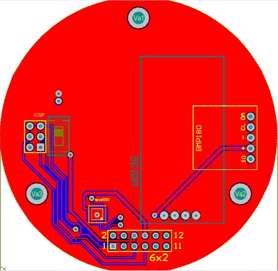
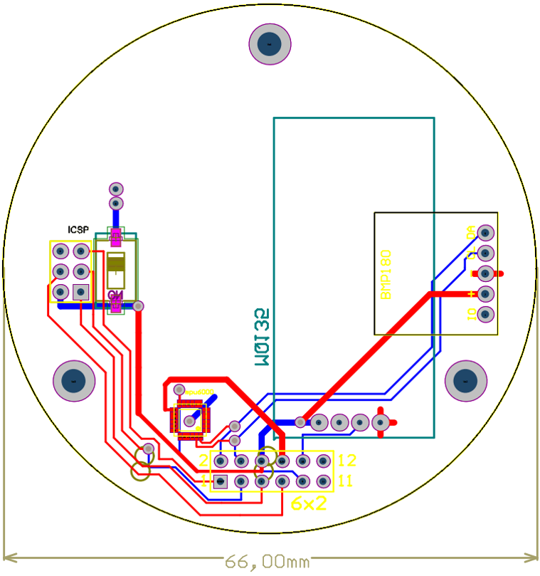
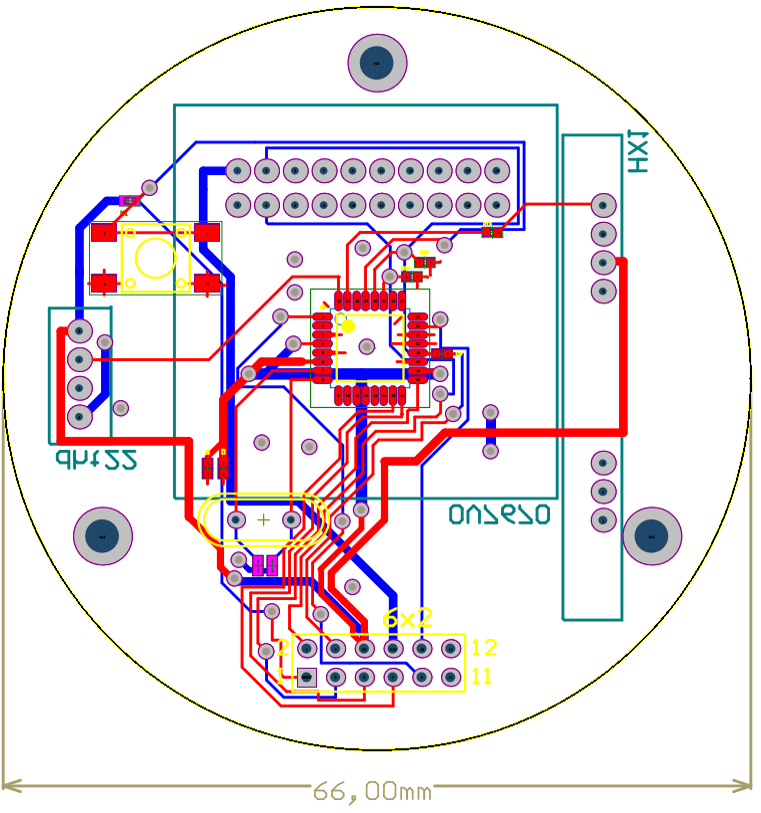
The PCD CanSat is divided in two different PCB layers:
First PCB
The next images show the tracks of the top (red) and bottom (blue) layers, and the final PCB with the ground planes
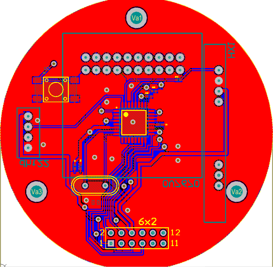
Second PCB
The next two images show the tracks of the top (red) and bottom (blue) layers, and the final PCB with the ground planes
Andrés Roldán Aranda, Printed Circuit Technoloy, Winter 2014. (ETSIIT), http://electronica.ugr.es/~amroldan/asignaturas/curso14-15/printed_circuit_technology/contents (Accessed). License: Creative Commons BY-NC-SA
Andrés Roldán Aranda, Printed Circuit Technoloy, Winter 2014. (ETSIIT), http://electronica.ugr.es/~amroldan/asignaturas/curso14-15/printed_circuit_technology/contents (Accessed). License: Creative Commons BY-NC-SA
For more information about using these materials and the Creative Commons license, see our Terms of Use.

