Exercises


Exercise 1
The objective of this exercise is calculate the power disipated by this heat bed. We can obtain all information about this bed from the Altium project provided by the teacher
We can see a PCB with many tracks. Each track is a resistor which dissipate power and as we know:

Using Altium we can measure the length and the width of the tracks, there are 4 traks in pararel with 7.809 m of length and 1.1 mm of width each one. Considering the thickness 17.5 µm the resistance of one track is 6.94 Ω and the total resistance is 1.735 Ω.
Finaly, the current through the input connector is:
Finaly, the current through the input connector is:

If VDC = 12 V, then the current is 6.92 A and the power disipated in the heat bed is 83 W.
Exercise 2

Solution proposed by Sharif Alhusein Raie (2019-20)
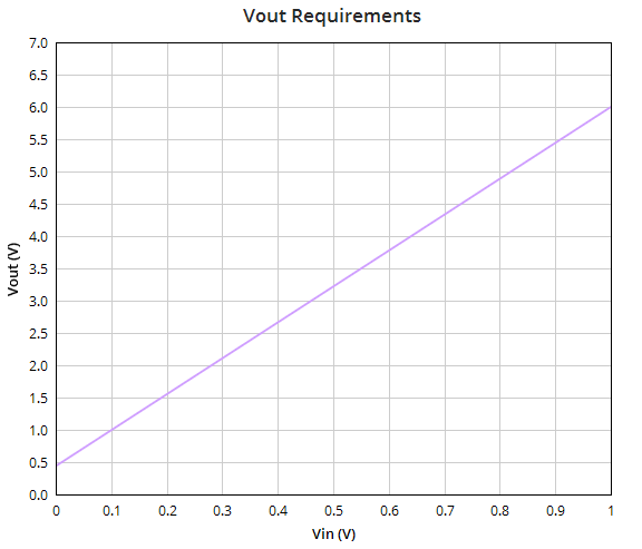
We should design a circuit whose transfer function is described in the graph above. As we can see it has an offset of 0.44 V. The gain of the amplifier is described by the slope of the graph and it is about 5.56 v/v. The analytic description of this function is:

I propose the circuit below, let analyze it.

It consists of a non-inverting adder hose expression is:


Then we can deduce:


The next step is to choose a value of R1 and R2 to obtain the required gain. Remember, we can use only resistors from the series of 5% tolerance.
For example we can use R1 = 3 KΩ and R2 = 47 KΩ. With this values, we obtain a gain of 5.555 V/V.
Then we have to implement Vx with the elements available. For example, we can use a voltage divider, but we must be careful, because in this case we will change the circuit response.
For example we can use R1 = 3 KΩ and R2 = 47 KΩ. With this values, we obtain a gain of 5.555 V/V.
Then we have to implement Vx with the elements available. For example, we can use a voltage divider, but we must be careful, because in this case we will change the circuit response.

In this case Va would not be what we wont and the gain would change as well. Unles Rth << R3, in this case we can despise Rth.
For example I will use R3= 75 KΩ, RX1= 100 KΩ and RX2= 820 Ω. Then Rth= 813 Ω
For example I will use R3= 75 KΩ, RX1= 100 KΩ and RX2= 820 Ω. Then Rth= 813 Ω
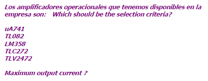
Finaly, we should choose one operational amplifier from the list above. The selected amplifier should be single-supply and it should be able to supply a maximum current of 60 mA.
However, none of the aplifiers provided can supply 60 mA of current.
For this problem, I suggest using two Operational Amplifiers in parallel, so each one should supply a maximum of 30 mA. For example, the LM358 can supply 40 mA.
So the definitive circuit is following:
However, none of the aplifiers provided can supply 60 mA of current.
For this problem, I suggest using two Operational Amplifiers in parallel, so each one should supply a maximum of 30 mA. For example, the LM358 can supply 40 mA.
So the definitive circuit is following:

The function of the resistors Ro1 and Ro2 is avoid current flow from one Operational to the other. They should habe small values, for example 20 Ω.
Exercise 3
Ohmic and dielectric losses for microstrip on a PCB
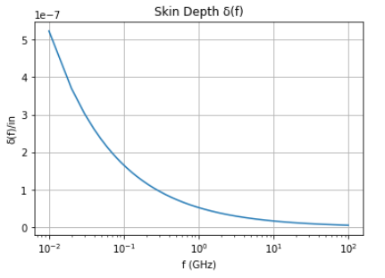
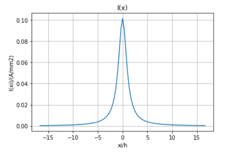
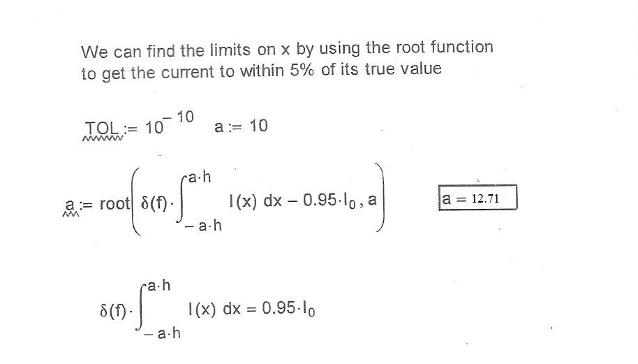
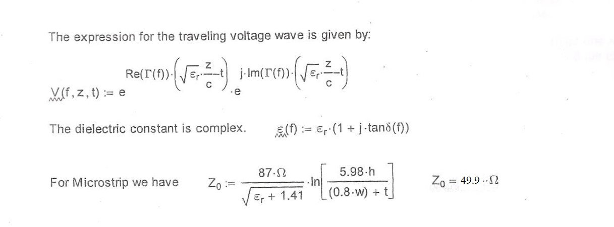
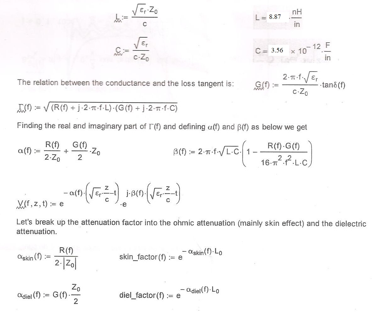
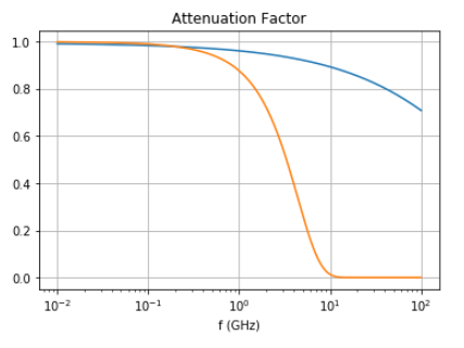
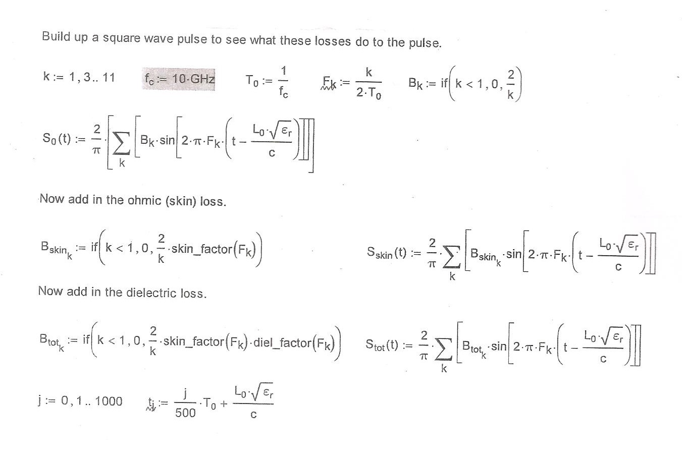
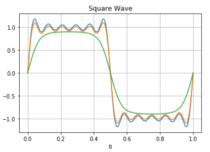
The propouse of the exercise is to calculate the effect of skin depth, dispersion and dielectric loss as a function of frecuency on the attenuation of a square wave in microstrip of length Lo.
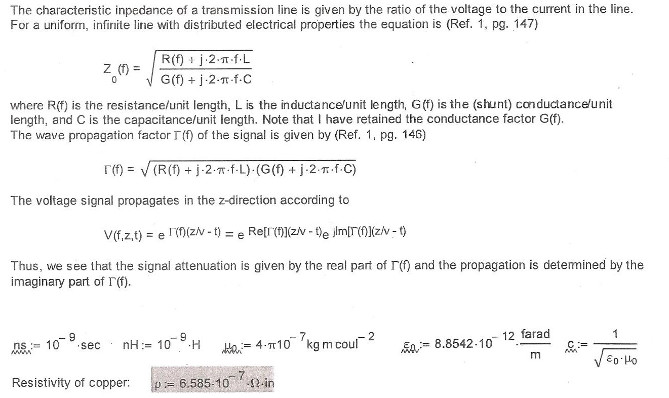
These parameters are for FR-4


